 |
| The repositioned fuel manifold. I will monitor the heat from the red, boxy March pump to see if I need to insulate it from the diesel lines. |
Well, it's been some time since my last post, but I have not been lazing about in the summer heat. Quite the contrary: I have been
getting the lead in by prepping the place where it will go. This has involved an array of modifications, such as the relocation of the fuel manifold from the side of the "under-stairs" to the saloon, to the building of an otherwise unobtainable battery box, to the shoring up of the floor to take the third of a tonne of batteries aboard, to quite a number of wiring decisions, crimpings and savings.
 |
| Access to this plumbing had to be maintained. |
Above is the standpipe and the newly relocated fuel mainfold. This needs access from above, and I have decided to retain the existing first step of the new companionway to the saloon because it matches the new space I've devised and constructed.
 |
| The first box I bought. The second I had to build |
First acquired was the hard-to-source (a couple of calls to a B.C.-based distributor were needed, as is often the case with the weirdo form factors I seem to require) L-16 four-battery box. This allows side-by-side storage of the batteries, meaning the customary roll of the boat both mixes the electrolyte more effectively and keeps less of the lead plates uncovered by it, assuming we keep the electrolyte levels at their proper volumes.
 |
| The four L-16 batteries' box. There's about one inch either side of it. |
Critical to success so far has been "dryfitting" and plenty of measurement. The spare area in this spot is less than a sheet of letter paper, and measure twice, cut once is only the start of things.
 |
| I often have an audience aboard when I'm not grinding or drilling or exercising "sailor talk". This bird thinks I need a bigger rode bucket. |
|
The second battery box, for two L-16s side-by-side, required lumbering around. I went with 3/8" inch which is confusingly labelled 11/16th, but as bigger is better in some respects, fair enough.
 |
| Mitre-cuts could have been better, but the workshop's bloody table saw was out-of-order. |
|
The results, me being not a great carpenter, were rough, but strong. I fastened the plywood pieces together with brass screws (not that I plan on getting this box wet, but they were the right size) into pre-drilled holes.
 |
| Eh, not bad. The corners are plumb. |
The dry fit here consisted of inverting the box and dropping like a slightly oversized hat onto two adjacent batteries. I've given some space to spare in case of battery swelling, but I also have a battery temperature monitor to cut charging should that be an issue. I won't equalize, ever, and
court thermal runaway without a) plenty of
ventilation in case of hydrogen production; b) plenty of "live monitoring" (no equalization voltages while underway, for instance); and c) careful attention to the proper voltage setpoints by confirmation not just from the system's intrinsic monitoring (either the charger or the MPPT output or the alternator's regulation, but via
decent voltage metering.
 |
| Close, and a cigar. |
|
Another dry fit involved both boxes plus a partition I would eventually cut down to the same height as the battery boxes.
 |
| Note to self: Do not do this again in a flat-roofed workshop in July. Thermal runaway detected. |
Next came the hot work of glassing the box to strengthen it and to seal it...it's supposed to contain battery acid in a worst-case scenario, after all. I considered fastening quarter round at the corners (or exterior metal clamps), but I filleted out all the seams extensively with epoxy and fibreglass cloth and I don't think it was necessary, nor did I desire an overly snug fit for the batteries.
 |
| Not pretty, but pretty thick. I later Multimastered off the more egregious bubbles and blemishes. |
While all that set up (which took hardly any time at all and I had one pot of epoxy go all jelly on me), the inverter went in.
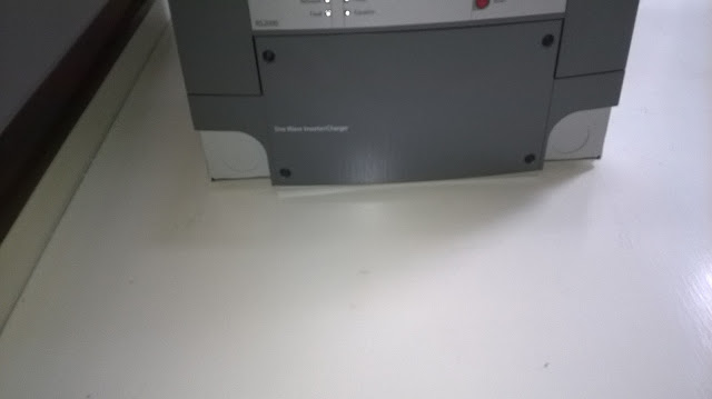
The inverter/charger is a 30 kilo beast and there's now six bolts in the head that I'll have to back with plates and then cover with a shallow plastic lid. But this was the logical spot in terms of weight, short (and expensive) runs of the required 4/0 ga. DC conduit and ease of access. We gave up two coat hooks.
Once again, the purchase of a
proper crimper,
stripper and other
electrical wire work supplies is paying dividends. All this improvement to the boat's electrical systems is expensive but also will succeed predicated on proper installation, which is also a factor in the durability when faced with the harsh marine environment.
 |
| AC IN 10/3 marine-grade, labelled, clear heat-shrunk and prior to putting in the strain relief. |
I like to label because I literally get a better understanding for my underfamiliar tasks thereby.
 |
| AC IN and OUT installed with strain relief. The AC IN goes to a 30A breaker on the AC panel, and the OUT goes to a Blue Seas panel breaker that keeps SHORE and INVERTER well apart. |
Shoving the inverter's AC wiring to one side, I did a dry fit of the Two-Box and the Four-Box to check my measurements.
 |
| I don't realize when it's getting dark enough to justify a flash because I'm a carrot-munching sailor. |
I threw in the token partition between the battery area and the plumbing/fuel area. It's angled slightly to permit a seacock lever to be rotated fully.
 |
| I subsequently tidied up the glassed-up box, although it's never going to be seen except by the crew. |
I also took the opportunity to shoot the camera in the midship bilges. These limber holes proved essential to fastening the threaded rod I'm using for battery box securing.
 |
| Very little rust, which pleases me as accessing this area for painting would require removing the floor. |
|
 |
| I am not convinced this "previous owner" work is to code, but it looks secure. |
Next, everything was removed and the area was drilled to take the threaded-rod for tie-downs. Basically the two ways to secure a battery box are with strapping, either of the
webbing type over the battery box secured to padeyes or directly to the boat, or via
lumber or angled metal drilled to take fender washers and nuts. I went with the latter because the boxes have very little room to move inside the "further" box of the stairs down to the saloon, and because I can further secure them by locking the stair steps that will allow access for maintenance and inspection.
 |
| The deliberately offset "sliders" for the dropboard-like partition. |
 |
| The partition in place. All this does from a functional point of view is stop water from a cracked hose spraying into the battery compartment. It wouldn't really stop the battery boxes from shifting if we had a lurch strong enough to shear the threaded rods. |
Drilling the rod holes involved feeling around to make sure I didn't hit something I'd regret. The threaded rod bottoms out on the heavy steel plate into which the keel tank inspection lids are bolted and serve an auxiliary support function to the wooden shoring I fastened beneath this floor a few days ago. Every bit helps, although this floor is secured to steel framing and even 750 pounds of lead is not going do much over this area.
 |
| The doubled threaded rod in place |
The threaded rod has fender washers and nuts below and above the floor. When the batteries are all in and wired up, I will cut 1/2 inch white oak planking and secure the boxes with the same arrangement and cut to fit. Only then can I rebuild the saloon stairwell, which will project somewhat more into the saloon and will make the galley slightly more snug...but in a good cause. It's just going to make one step in and out of the galley an option.
 |
| Looka like it fits. The fibreglassed battery box will get its own lid later on. |
The dry fit with the threaded rods confirmed my measurements. Tying the tops of those rods, which will be trimmed for height, together should make the boxes very secure. They'll have nowhere to go, really, even in a complete inversion, once the steps are in and locked. But let's not dwell on complete inversions.
As I had the gear to hand, instead of cleaning up, stowing the multiple tools I had out and calling it a hot, hyperextended and dirty afternoon, I decided to drop two of the six batteries that have spent a few weeks on my pilothouse deck into position. It worked surprisingly well, although I'll bring my son down tomorrow to work the fall as I position the last four L-16s in the "four-box".
 |
| Nice fit, buddy! |
I was going to do this in two installments, but clearly, the project has grown to justify
Getting the lead in, part 3: Powering Up. Watch this space!


No comments:
Post a Comment