 |
| The greatest hoist ever executed. |
This post describes, in graphic-heavy detail, how I've built what I hope will be a durable engine gantry for the new diesel mounting, coupling and alignment procedure. It turned out to be yet another in a long line of "boat learning experiences". I'm posting this with loads of photos as I was asked to relate my experience with this project, so please bear with the load time.
Getting the diesel into the boat recently was
comparatively easy...about an hour's work with a guy on the Polecat crane, me and a friend shifting and using radios and whatnot.
The typical marine diesel engine, for the uninitiated, must sit on four "
motor mounts" bolted to engine stringers, fore-and-aft steel girders (in
Alchemy's case; f/g boats have either solid or wooden-cored engine stringers covered in a thick, reinforcing layer of fibreglass), and aligned between the engine coupling (the heavily built spinning disc at the back of the engine), and the propellor shaft coupler, a similar metal disc about 12-15 cm wide at the inside end of the propellor shaft.
 |
| Typical marine diesel mounts. Photo (c) "Dual-Flex" |
 |
| Typical "drive-saver" coupler insert designed to reduce vibration. |
In most boats, this has meant a quite exact alignment, as the flat surfaces of the shaft and engine coupler must "mate" as close to exactly as possible.
The reasons are twofold: The couplers' surfaces are very smooth and are secured by three or four or even more bolts; a more close-to-perfect fit means a tighter fit, meaning the bolts are evenly stressed. The second reason is that misalignment, even below the level of casual observation, can induce both vibration and destructive wear on the engine's drivetrain and the "stern tube", the glass or metal pipe that encloses the prop shaft on the way out of the boat.
Misalignment can wear all the parts of the drive train, from the crankshaft and bearing inside the engine, to the prop at the far end. The engine prematurely wears, the stuffing box can overheat and fail, the expensive shaft can become scored and worn, and the prop' s blade can wear. The cutlass bearing can fail. Worse case could be an engine seizing or the shaft failing: Boom, you can have a nice chew out of your rudder as water comes hosing into your engine compartment. You
do have tapered wooden plugs and a prayer shawl back there, right?
So the so-called "solid" coupler requires careful alignment using an interesting little device called a "feeler gauge". Essentially a little jacknife with several little slips of metal of differing thicknesses, this gauge tells you how close to ideal the coupler surfaces are. Considerable dinking around with the engine mounts can be involved, little 1/8th turns of the heavy, and by that stage, load-bearing bolts in the motor mounts, to raise or lower the engine fractions of a degree to obtain as close to "completely aligned" as is possible.
While it is quite possible to do all this with wedges, crowbars, foul language and a small quantity of blood sacrificed to the sea gods, my particular situation called for some inventiveness. In short, I needed an engine gantry, something to allow me to haul the engine up and down over its stringers (the longitundinal beams to which the motor mounts are bolted) and forward and aft until I found the exact spot needed.
 |
| Ideal, but expensive and way, way too big to fit in the pilothouse. |
 |
| Great for a car, not for a boat with a "diesel pit": you can't lower the engine past the legs. |
|
|
 |
| I was not sure I wanted to drill holes in the pilot house deck, bolt, back and brace this underneath. Cool gadget, however. |
I
solicited advice from my fellow sailors, and seriously considered making something out of steel pipe and Kee Klamps, with which I am familiar from work in the film industry...
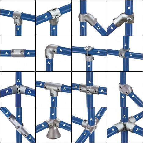 |
| Not cheap, but reusable and essentially man-sized Meccano. It was hard to resist. |
The Kee Klamps would have been used as pictured. Their use seemed so practical, if pricy, that I started to design in earnest:
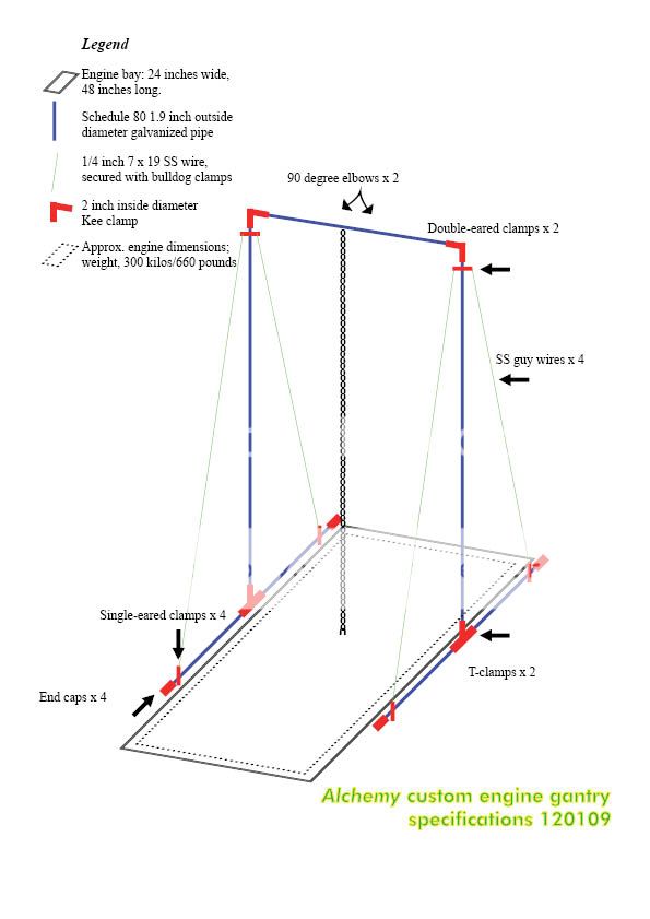 |
| Oh, Kee Klamps, we would have been good together...but you cost top dollar. |
|
|
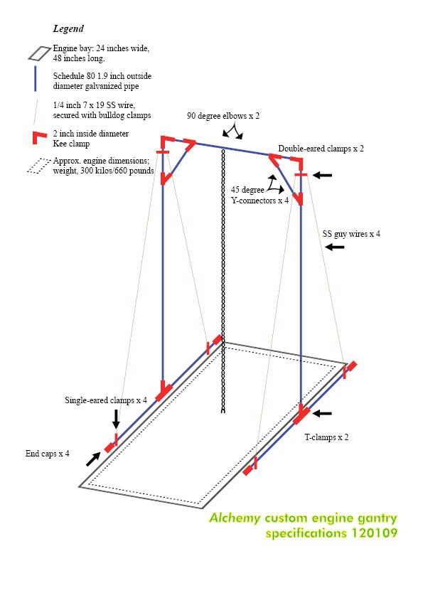 |
| I even did Version 2, beefed up at the corners |
But the Kee Klamp Solution, beautiful and skinny as it was, was several dollars too far. I even had some "thinking out of the box" suggestions, like a tripod affair:
 |
| Not enough spread on the load bearing surface, and the engine would snag the chains. |
 |
| I'd have to take the roof off. |
So in the end, decided to build in dimensional lumber: Two triangles, cross-braced and bolted, should have done it. I got "designing", a dignified term for engineering of the level usually found on the back of a napkin.
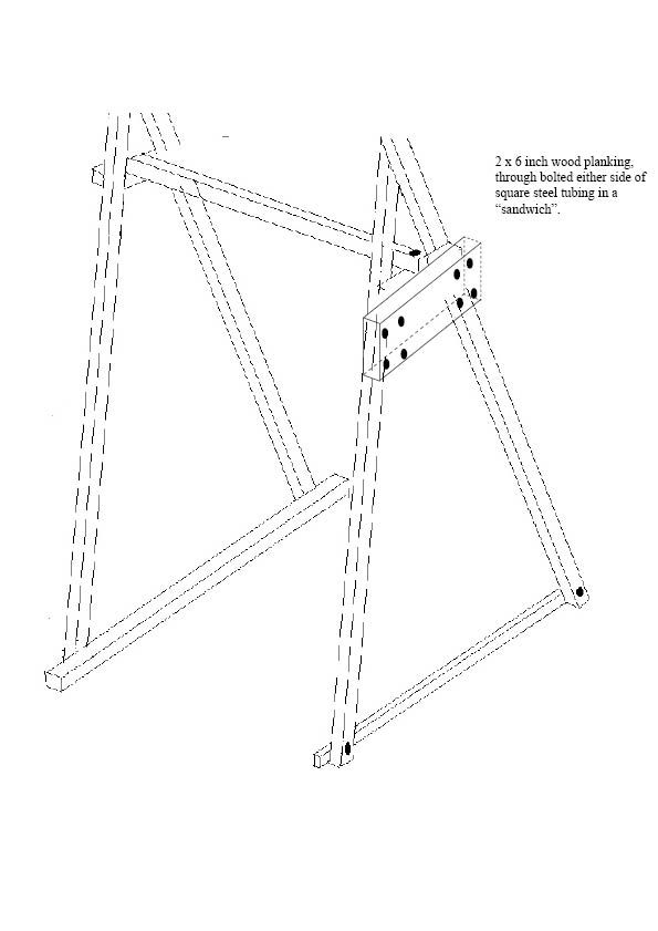 |
| I started by modifying my engineer friend's basic design. |
Then I actually took measurements and made modifications.
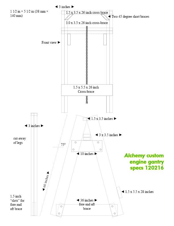 |
| Then I smoked crack. Things got a little out of hand. |
The opportunity to learn through building and the chance to save a bit of money (I estimate I spent $80 on all the bolts, screws and lumber) meant I could live with inelegant and heavy if it was strong enough to persuade me to get under the suspended engine. No joke...I could get killed in a fairly vivid fashion (arrgh, pump the bilges...) if I failed to cobble together something sufficiently strong.
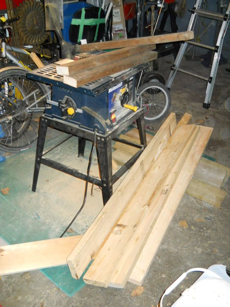
I went with KD-grade construction spruce 2 x 6s, about five 12 foot lengths.
 |
| Reminder: Sweep garage |
Using my table saw top as a work area, I first cut the cross-beam, which would end up "floating" and held only by the engine weight, on braces.
 |
| One of my oldest and best-performing power tools, plus a very manly drill bit. |
This was to enable me to easily reposition the beam, and thus the hoist's vertical drop, some short distance fore and aft.
 |
| That very long racheting wrench thingie was a deal. The radius means you can crank fast enough to warm up the nuts, and what man wouldn't like that? |
The beam itself was made from hemlock 2 x 4s I salvaged from the rebuilding of our breakfast nook off the kitchen (it used to be a drafty, sinking "mud room"). Unlike modern lumber, these were a lot closer to being 2 x 4 inches, and hemlock is strong. Thinking I'd double the thickness, I eventually decided to triple it. I did not wish to here a single creak. Through-bolted with six inch long, half-inch thick SS bolts, washers and nuts, it seemed pretty well tied together.
 |
| I liked using a template, to a degree |
I decided I wanted a pair of 2x6s for each of the four "legs", and that the base 2 x 6 should be mortised in between them, and then double-bolted for strength. This required a bit of geometry to compensate for the angled legs, so I made a rough template.
 |
| Not as inaccurate as it looks. |
 |
| I saw things above plastic because beneath is the drain for the horse piss: my garage was built as a stable. Not that I intend piss of any kind to happen in the garage. That's what the garden is for. |
|
Dicking about with these cuts took some time. Knowing what you want and having the experience to take a shortcut, or to see that one might exist, are different things.
Fortunately, years of low-grade, faffing-about house repairs mean I generally can lay hands on the right tool.
 |
| It's Black and Decker, a crap brand. However, it was on sale for $29 and the tippy plate thing comes in quite handy when the alternative is a plastic mitre box and calories. |
Or, rather, the "right now" tool.
Eventually, I had four more or less equal-length gantry legs with mostly similar trapezoids cut out of their insides.
 |
| Like your prom date, it's even worse up close. |
I had a slight change of plan when it came to making the "triangles".
 |
| I needed good light and level concrete for this bit. I got good light. |
I decided I wanted ones with brushcuts.
 |
| Apparently, I was on the level |
Things were coming together. The keen eye will note my Honda 2000 genset. I run a crappy line to the garage, just for lights, pending the rental of a backhoe to dig the requisite legally deep trench, and I don't like to run power tools AND lights in there as it could trip a house breaker 100 feet away. So I use the Honda. Handy little bugger.
 |
| Based on an abandoned IKEA bookshelf for frost giants. |
So I had a brace for the forward face, a brace over the top, and two "keeper" planks to center the hemlock triple-width beam.
 |
| So clean! (Not the garage, the gantry) |
That was basically that. The "open" side would allow the transmission to clear the gantry, or so I thought.
 |
| This is the reality of two boats, no car, folks. And yet if I had a car, I probably couldn't swing even one boat. |
The problem now was to disassemble the thing and get it down to the boat.
 |
| Nice lashings, at least. |
My customary mode was, to put it bluntly, overtaxed. Riding this over a little bump might, I thought, either kill me or snap my frame, bike or trailer.
 |
| Cockles, and mussels, and lumber, ei-oh. |
The gantry weights over 100 pounds/45 kilos, after all. So a hand truck or dolly that can convert to a four-wheeler and can take 800 pounds of weight was needed. After the Makita drill, I use this thing all the time. A great deal I got for about forty bucks.
 |
| It only *looks* like a DIY trebuchet. |
After much personal heroism and unappealing grunting, I humped this Frankenwood assemblage down to the boat, and used the handy deck crane.to haul these chunks aboard. Inevitably, they required even further deconstruction just to fit down the companionway.
Much unrecorded swearing, bolting, noting the base was one-half-inch too narrow for optimum, recutting, rebolting, drilling and screwing, the "wide stance" frame was in place:
 |
| Pit, but I hope no pendulum. |
This length of line was fine for deposit via the Polecat crane, but I replaced it with a short piece of chain to lessen the gap between the beam and the engine.
 |
| Not much point if I can only get it partway up, said the actress to the bishop. |
I cut some chain to fit the beam and...
 |
| Suitable for hoisting diesels or torturing heretics. |
...making sure I was more or less centered over the engine's mass, so as to avoid a nasty swing when I cranked it free...
 |
| It shifted a bit because I'm not quite zeroed on with the hoist and chain positions. Easy enough to fix, however. |
,,,hoisted away. The chain hoist is a one-tonne model I got from Fastenal on sale for $69. Needless to say it will come in extremely handy for a) installing water tanks, b) installing half a tonne of batteries and c) removing 600 kilos of lead ingots from the forepeak put there for trim purposes. Which infers the amount of tools, chain and anchor our boat is meant to sport.
 |
| WHEE! |
 |
| DIESEL GOES UP, DIESEL GOES DOWN...yay... |
The chain hoist is one of those devices (much like the similar winch) that you think you can anticipate how it works, and then you use it, and it is actually far easier. I can lift this engine with one hand on the chain, and lower it precisely. It's a fine thing, this hoist. Particularly on a steel boat. Looks the part, this part.
 |
| Ok, stop already. You can play with it tomorrow. |
And the rather elaborate and painstakingly constructed (because I am clumsy, hence pain) engine gantry thingie?
Fabulous. Nary a creak, not a shift, groan or wobble. The floor of the pilothouse is similarly unprotesting. I am well-pleased.
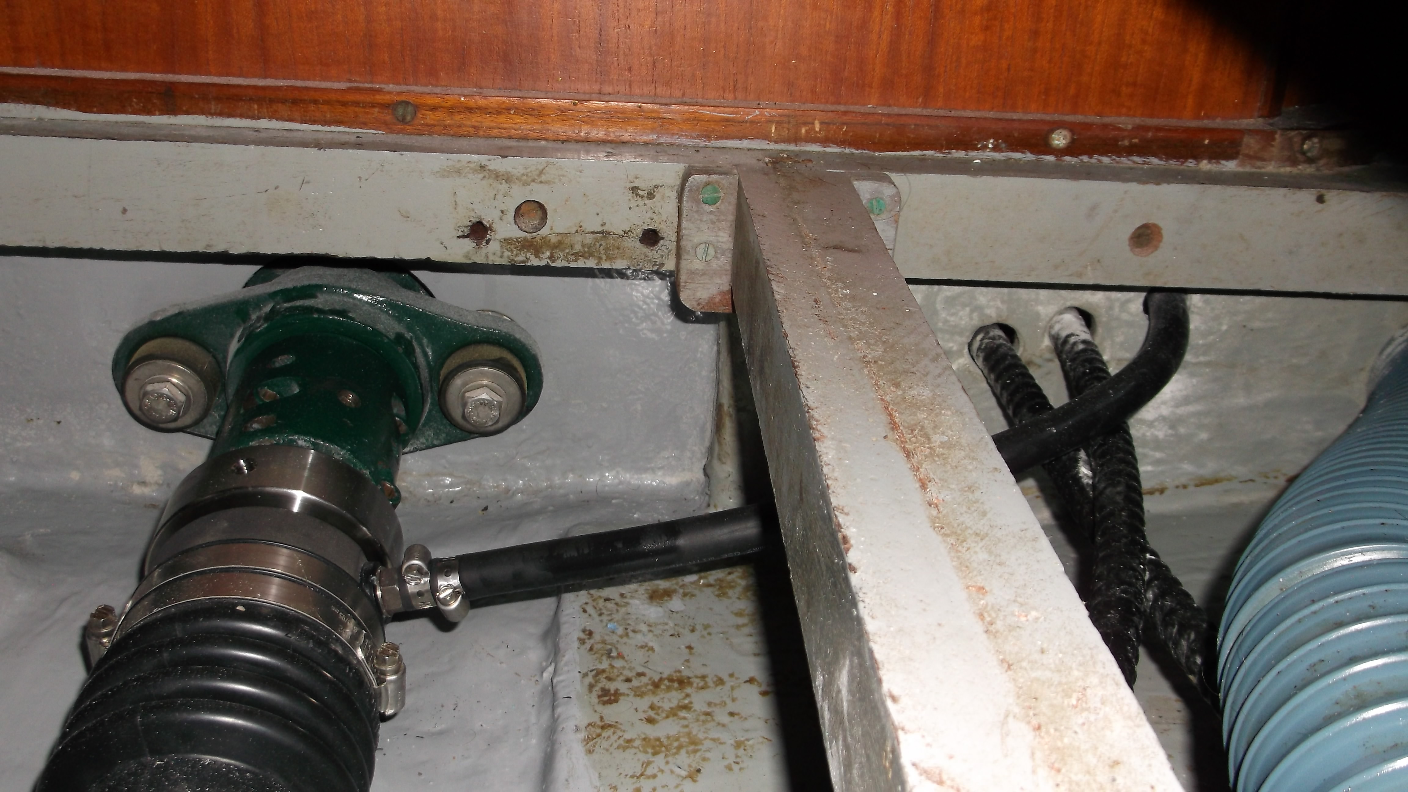
 |
| Four feet to the shaft seal? Where's my measuring tape? |
As for the ultimate reason for all this levity, or rather levitation? To get the new engine on these flexible feet, to bolt the coupler to the Aquadrive unit, to bolt the
Aquadrive unit to the shaft, gird as it will be with that PSS Shaft Seal thingie, and to clap on a four-bladed feathering propellor fit to power us off lee shores of exceeding remoteness.
 |
| Eventually, it should resemble this. This is very cool, if you
understand the issues with motoring a small boat in a seaway. Saves
vibration, wear on the drivetrain and shaft misalignment issues. Photo (c) http://www.botanybay.org |
And that's the boat that Jack built, or is building. Further reports shortly.


