Copyright (c) Marc Dacey/Dark Star Media 2006-2020. Above photo (c) Marc Dacey. Powered by Blogger.

2013-02-06

Propositioning, or getting a right shafting, Part 1

Bear with me. I zinc we're threaded somewhere.
Warning: This could get pictorial. Heavily so. And longer-winded than even usual.

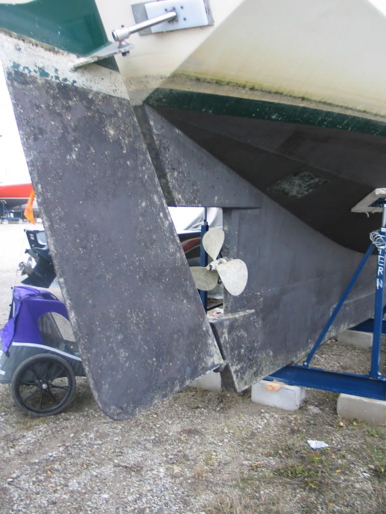
When last we visited the beached mechanic's nightmare known as S/V Alchemy, the rudder had been removed and the old three-blader rudely pulled off its somewhat grubby shaft. In order to satisfy certain concerns about El Propo Grande's blade tip clearance, the new Variprop was put on "finger-tight".
So very pretty


Plenty of clearance all around. Collar shaft zinc optional.
Cutting remarks.
Seems straightforward...nom, nom, nom.

As it turned out, the clearance issue was no issue at all. What loomed next, however, was The Problem of Whip and The Question of Line Cutting. The problem of whip involves the degree to which the shaft runs unsupported beyond the bearing in the stern; even though I could extend it to include a Shaftshark or a similar line cutting device and a 1 3/8th inch thick collar zinc, this would mean unnecessary whip, which is bad for the bearing and bad for everything up to the thrust bearing, the first "hard spot" in the new drive train. See that grey cone on the end of the prop? That's a zinc, and it will suffice. In the equivalent of that zinc space on the shaft (about 1.875 inches at last measurement) will go a Shaft Shark:
The function of this is clear to anyone who has driven over fishing nets, half-sunken line, or even the sturdier sort of plastic bag: If you can chop something to bits before it fouls your precious, precious feathering blades, you should.


Practically modern art, in my view.
Regarding said bronzed masterpiece, one of the first things I purchased for purposes of refitting Alchemy was this glittering and expensive propulsive chunk of German engineering. If I bothered to mull on it overmuch, I would note that it sat in its box for nearly six years before even getting dry-fitted. Write your own rude joke here.

It does not bear too much self-criticism, however, as that time was spent acquiring skills of both land and sea varieties, restoring my original boat (Valiente) to make it more appealing as a loaner, putting my wife through teachers' college (if not, alas, employment as a teacher as of yet), seeing my son complete several courses of sail instruction and get large enough to stand watch and be more crew and less cargo; and sundry other household and family matters of varying degrees of compulsion and distress.

Did I ever mention I'm the owner of a freelance design and writing business (meaning I find work, I don't go to work) and a landlord (meaning I fix what's broken)? Yeah, boom goes most of the scheduling and good intentions. Let me be a horrible warning to all. Do not attempt without a lottery win and years in the trades.

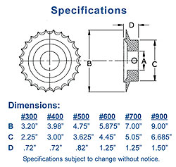
Irrespective of my whingeing, the important part of this particular post is that I calculated, correctly as it seems, that the new "Variprop, modelle D-107, 4-Blatt, 19 x 15" would fit the space occupied by the the former 18 x 13 'fixed", meaning non-feathering or folding, three-blade. This relatively unworn prop will cleaned up and will become a spare we will bring with us.


In 2007, space was terrifying. So was the state of the bottom paint.
The Variprop installation was so widely separated from its original purpose in time by the decision to re-engine. This ultimately meant a number of other sub-projects had to happen, and are now close to happening, or are very nearly at the point of having happened.

(God help the people reading this whose first language isn't English.)

In order to obtain the promised Variprop benefits of "Ruhiger Lauf unter allen Bedingungen, super Schubkraft, keinerlei Vibrationen" (and honestly, who would not want that on a sea-going vessel?), it's going to involve a new shaft cut to the proper length.

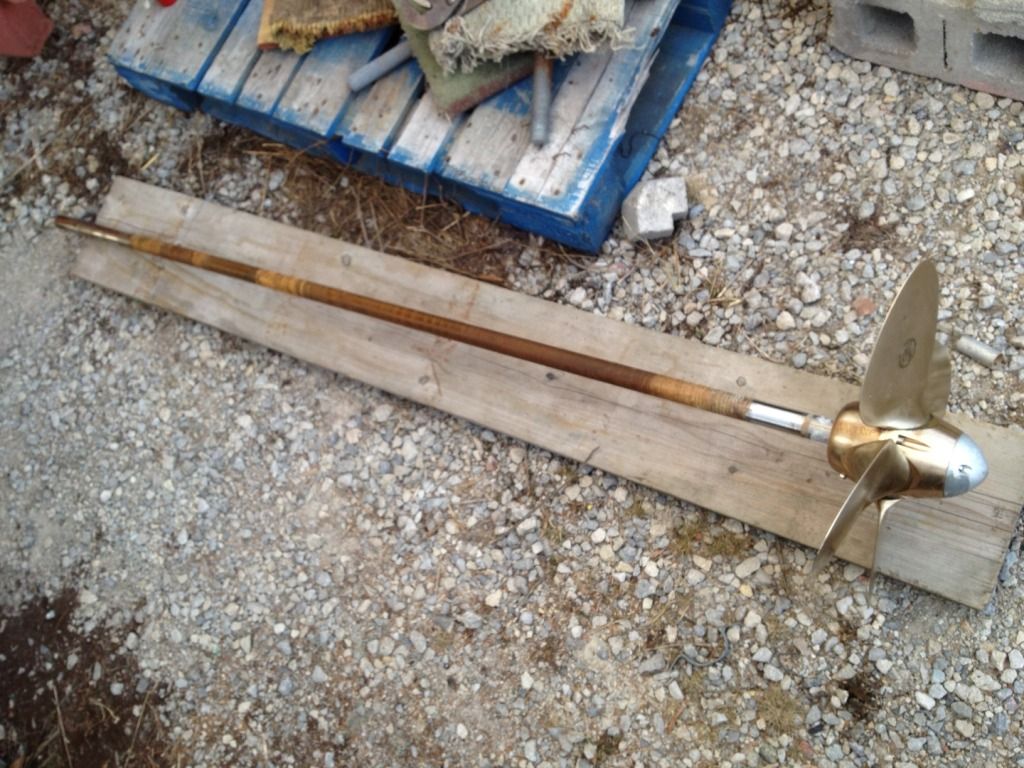
That involved the removal of the old shaft. Oh, my aching etc.

A rare appearance by your humble correspondent working up a sweat in -9C weather.
Said shaft was, probably due to the Thordon Elastomeric bearing being out of the water for so long, surprisingly resistant to removal.

I'm thinking this shaft is 304 SS. I want to keep it for the ship's stripper pole.


But thanks to our collective extreme manliness and a surplus of clean living, we extracted the metallic devil from its lair and removed the Variprop for a brief rest. The next time that prop is going on, it'll involve LocTite and a future in Seaworld.

Age has no bearing on it: This device is hardly worn and will be staying in place.

Of course, prior to the propshaft pull, we needed it to stay in one spot for the critical thrust bearing template construction and placement. In the "Aquadrive" system I've chosen to install, the prop pushes against a thrust bearing tied (by welding and bolts) directly to the hull.

Here's what the model for the fabrication, as created by Capt. Matt, looks like:

Now with real bevel angles
Picture all this cardboard being half-inch thick welded steel and it's all significantly more butch.
It's based on what he learned doing his own Volvo 55-Aquadrive-Autoprop installation a few years back, as seen here:

Showroom quality!
It's functionally identical to what I'll have, if differing somewhat in dimensionals, as we have, of course, different Massive Boats of Steel.

Still plenty of space in that bilge, even if you can visualize the waterlift, thrust bearing and wine cellar
 The little pulled-apart clothes pegs you can make out in the stern tube are exactly those. They are the right size to shim the shaft, in the absence of a supporting stuffing box, to more or less the center of the stern tube, which is necessary to align the bearing (the cardboard model), the "yoke" (the large green metal thingie) and the CV coupler (not pictured) with the transmission flange (the business end of the engine).  The space between the stern tube and the yoke will contain the packless shaft seal, a clever device that can be seen in the video below. A properly installed PSS will keep ALL water out of the boat, a desirable state of affairs in a steel vessel.


After the construction of the thrust bearing fabrication model, we needed to rough in the engine's eventual position. This was a "one-hander" job, thanks to the engine gantry I built last spring. 

More up and down than a spring-mounted whorehouse demands proper support for one's tackle

The engine stringers (the fore-and-aft welded girders to which the engine mounts are bolted) needed approximately four inches of height to raise the engine, mounted more or less at the halfway point on the engine mounts, to be at the proper height to couple with the Aquadrive.

Two by fours haven't been either two or four for some time. All this is "four".
It is therefore necessary, in order to gain this height and to give the engine mounts a very secure attachment to the hull, to fabricate steel "pods" or "boxes", which will be welded in place onto the stringers, primed, painted and drilled at the right places to take those mounts.

The mounts themselves are markedly larger than the ones supplied with the engine, and are an integral part of the Aquadrive system. They are called "soft mounts" and this differing type of rubber on the inside has both a vibration dampening effect and allows the engine to rumble with a touch of movement, thanks to the CV (continuously variable) joint attached to the transmission flange.

The result is a much quieter installation in boats made from metal, not generally known for silence underway. And as there is a bit of "give" in the engine's attachment to the boat (but not at the shaft), alignment issues and wear associated with misaligned, as can be the case with solid couplings, is no longer an issue. So, come for the quiet, stay for the reduced wear on the drive train.

But soft! What mount through yonder lumber pokes?

This stringer augmentation operation also gives a bit of desirable height and access to the bottom of the engine (the oil sump and various hard to reach places). I feel it's a prudent and tidy practice to slip in a roasting pan or some similarly easily bent metal container with a pad or two of oil-absorbent material. Even the best, newest, and torqued-to-spec engines can shed various fluids, and this is a cheap method of confining whatever mess may occur. And if a failure of greater proportions (a seal failure, for instance) does occur, the oil pad will reveal under what part of the engine the problem is located.
This gap matches within 2 mm the length of the CV joint and the flange adapter.

As can be seen above, even before the engine is dropped onto the mounts, which are there for final, "fine" adjustments, we are pretty close. While the Aquadrive can accommodate a fair degree of misalignment, the ideal installation as I understand it is to bolt together the entire set-up to as close to zero-degree, perfect alignment as possible. This means when you are trying to motor off a lee shore in rough chop and the boat is being thrown around, you are going to have all the "play" the Aquadrive system offers, meaning you aren't going to snap something because your hull is flexing or you are getting slapped through sixty degrees of roll.

Yes, touch up paint and a little Scotchbrite work is required.
In retrospect, one problem that has cropped up was predictable. When I bought the Aquadrive gear, I had a Westerbeke W-52 with a Borg-Warner mechanical transmission. Learning that rebuilding that engine, which had only 1,300 hours in 19 years on it...but only 100 hours and two years under my care...would cost 90% of the cash required to buy a newer, more powerful, less thirsty, less polluting, lighter and smaller diesel, it wasn't hard to decide to pop for the Beta 60.

This, however, is a different transmission. It's a ZF 25 hydraulic and that flange is about 75% of the size of the adapter plate (the 3/4" thick piece of Germanic engineering that goes between the transmission and the CV joint) that I have in hand.

So I had to do some measuring. The Beta came with a shaft coupler, so I knew where the holes had to be.

Digital inches are cool. So are cheap micrometers
We'll call that "four point oh".


"Brent", the patient and helpful staffer at the fine firm that sold me the Aquadrive, suggested I could remachine the existing adapter I have to fit the CV joint and the ZF 25 flange:

That's a bingo.
In order to do that, however, the four new bolt holes have to line up just so:

The holes at 9 and 3 o'clock represent "so".
It may be clear from the above photo that putting the big holes on the outer "orbit" (the flange bolts) down by the smaller holes in the inner "orbit" (for the CV joint) would be tricky, indeed.

German engineering, natürlich, has already thought of this:

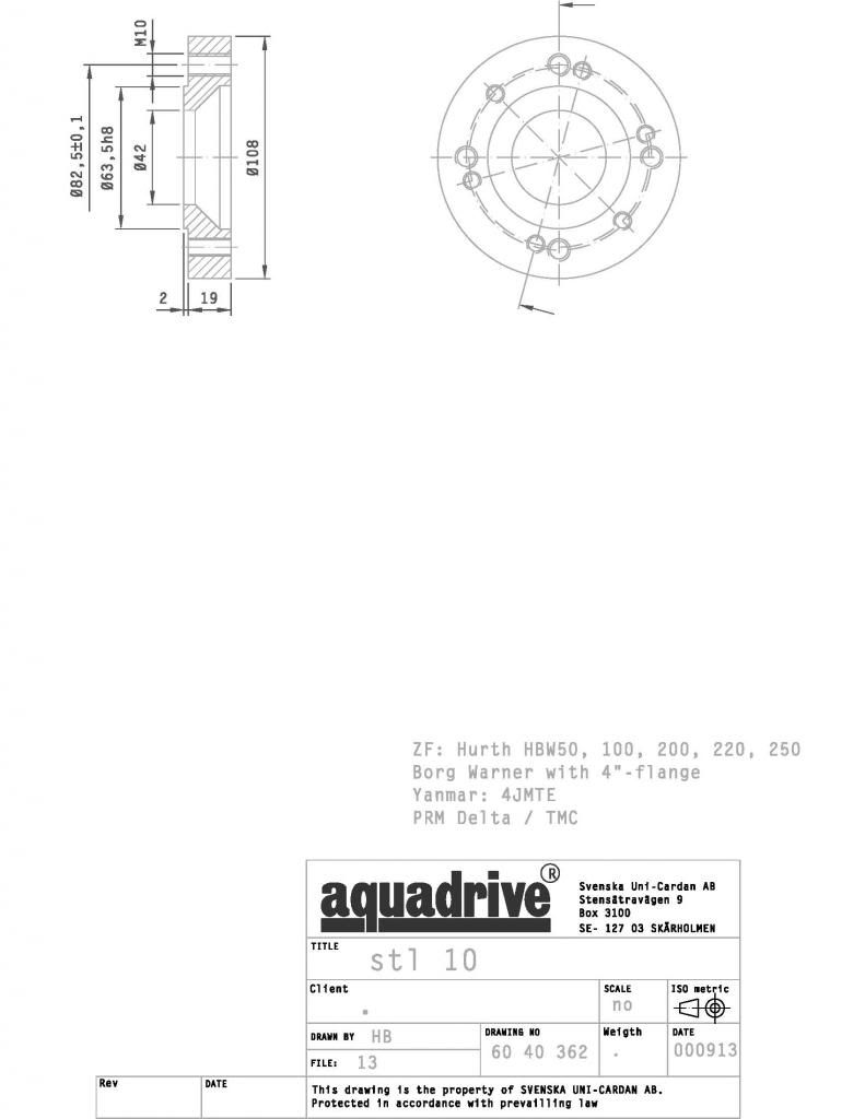
Yeah, I could've made this white space smaller, but I get paid for that sort of thing.
Note the cleverly offset big holes. So the nice man in Charlottetown is going to figure out the price of buying and shipping a couple of kilos of fine Teutonic millwork to Toronto, and if it isn't truly outrageous, I will have an answer.

If it is beyond the fiscal pale, I have a PDF to show a millwright here in Toronto from which to work on the existing adapter.

More or less how it will look when locked down.
So, after a fair bit of worthy and only slightly impeded progress, the status report for early February is as follows:

1) Engine stringer pods are ordered and are being fabricated. DONE 13.02.13
2) Thrust bearing for Aquadrive "yoke" is designed, is ordered and is being fabricated. DONE 13.02.13
3) New prop shaft has been ordered, and is the same dimensionals as the old shaft, but in higher-grade steel. ORDER CONFIRMED 13-02.07
4) Flange adapter is being priced. ORDERED 13.02.07 RECEIVED 13.02.22!
5) Shaftshark will be ordered this week. DONE 13.02.06 RECEIVED 13.02.15

To do in next week:

1) Confirm outstanding orders and find out availability of welder for thrust bearing and stringers, which should be ready in a week or so.

2) Confirm that new exhaust outlet is to be moved from starboard to port side; confirm outlet is to be 51 mm/2 in. OD.  Remove old bilge outlet sea cock. Note: Replace oil we used getting the damn prop out.

3) Measure and plan out exhaust system based on Centek or Vetus waterlift. Based on now-known engine height, work out angles for proper rises, etc. and confirm whether a transverse exhaust pipe or supported hose is feasible.
This is too good an idea not to consider. A siphon break is not needed as one side is always open to the air. Long-time readers will already know my disenchantment with these devices is profound.
4) Tidy up boat and reorganize tools for better access as you use damn near everything in this sort of job and reaching around a massive wooden pyramid in the middle of the pilothouse is getting old fast. Must obtain more clamps! Must search Canadian Tire flyer!

5) The engine must be hoisted high for the welder to get all around access. This means removing or hinging the lowest companionway step to create room to move in, and to cut transverse planking to rest the engine on at pilothouse floor level. Update 130215: Still sourcing the hinges, which need this design at a lower price and not as sturdy. Engine gantry is now modified to raise the crosspiece support about one foot and the floor-level planks are cut and fitted.

A launch is late April is a certainty. A powered launch is looking more likely after the last few days of work. Propositioning, Part 2 is here.


2013-02-05

Now, I'm no expert...

...but I try to take care around my boat work, partly because I don't want to learn the hard way and have to do things six times, and partly because I'm always conscious that I did not receive training in my youth that would help me in any respect in my current full-bore, hands-on operations. Humilty and paranoia are my boat repair and rehab tutors.

So yesterday, my knowlegeable friend (and an award-winning cinematographer) Capt. Matt and I had just retreated from both the cold and from hauling out a very balky prop shaft.

Apparently, the secret to motivating a dirty old shaft is "more lube". It was ever thus, or rather, thrust.


This is part of the whole "tie down the engine to the boat and the new prop to the engine" exercise, more about which will follow in a later, action-filled post. Or maybe two. It's a big topic.

And we see this through his car windscreen:


This leaning tower of cinder blocks seems sub-par to me

Now, I'm no expert in how to overwinter on the hard with vintage runabouts, and I don't know if it's just a maturing sense of competence or a basic feel for physics that made this seem a little dodgy in both conception and execution.

The hardest working square inch of pine wood ashore.  Picture the fate of the comically small fenders versus the five-ton crane.
Perhaps this is standard operating procedure for the owner. Perhaps my urge to back away on tiptoe so as not to create disrupting vibrations is related to the aforementioned refitter's paranoia. But that is one of the sketchiest things I've ever seen in a boat yard, and I've seen drunks urinating off bows in snowsqualls, boats casually dropped off cranes and trailers, and numerous drug deals.

Maybe some runabout owner will write to reassure me I'm completely off-base (like this boat very nearly is), or that it is Perfectly Safe. I wouldn't mind if the blocks were doubled up and rotated 90 degrees with each row; there's nothing inherently bad about that practice. This practice, however...

2013-02-03

Make and mend: Spares, DIY and overthinking self-sufficiency


A self-made man.
In the Royal Navy of centuries past, "leisure" was a fluid concept. Seamen of various grades, unlike officers, did not have set uniforms, although a certain uniformity of dress prevailed. Like officers, they were expected to provide their own clothing: officers would have tailors create uniforms from approved patterns and colours, while seamen would literally tailor their own clothing from issued "slops", basic items of clothing that could be altered to suit fashion, function or form.

To these ends, crews on Royal Navy warships would get one "afternoon off" each week for such "make and mend" work: the construction of new items of clothing, often from spare bits of canvas cribbed or purchased from the sailmaker or his mate, or the repair of existing clothing. All save the newest, perhaps impressed, crew would have the cutting and sewing skills necessary to create reasonably tidy clothing, and which would, while remaining individualized, hew to the general look of "seaman's rig".
Such skills as might be required after these sort of fun and games.
Perhaps contrary to the preconceptions of what "life before plumbing" was like, Royal Navy crews were generally cleaner, healthier, and, barring death or injury in battle, longer-lived than their shoreside relations. Many, although certainly not all, captains sought to maximize the lives of their crews, skilled and trained examples of which were in short supply, through food supplements (hence "limey") and basic hygienic practices. such as regular bathing, basic laundry, the airing of bedding and hammocks, and cleaning of the otherwise filthy bilges. Rudimentary as these methods may have been, they were generally far in advance of terrestrial habits, where "apply more gallons of perfume" still held sway.
Improved the grog, too.
"Make and mend days" were comparatively restful occasions for the working Jack Tar. They were a time to socialize, to perfect certain aspects of seamanlike skills of needle and knife, and to relax in a more or less sanctioned fashion, secure in the knowledge that most things were in good order in the wooden world of His Majesty's Ship.

Which brings us to the ideal of self-sufficiency and the reality of "only so much boat". The Royal Navy, tasked with the defense (or often the acquisition) of a vast, disjointed empire, had at its disposal ships constantly in a state of rot, cannon and musket-fire damage, and the material weakenings of sea, sun and wind. Depots of trained craftsmen, shipwrights and labourers, along with hard-to-transport materials such as masts, planks and cannon, had to exist in remote areas. Ships on dreaded blockade duty spent months and even years on station without "refit", getting occasional resupply at sea even as planks were sprung and sails were shredded. Other ships would cruise thousands of miles from the closest naval bases, and had to bring many tons of canvas, lines of every description, metal plate and ingots and the means to forge them, along with food and drink sufficient to keep large crews alive, if not particularly well-fed.
"Out of Madeira? The deuce you say, sir!"

The limit of wooden warship construction was some 200 feet/60 metres LOA. Larger ships would "hog" or sag under their own weight. Taller ships might and did capsize due to the weight of cannons carried too high. Nonetheless, given relatively strict limitations, it was not unusual for a medium-sized warship, such as a frigate or a third-rate "74", to be on patrol for a year or more without more than going ashore to fill water casks or to obtain a few animals for on-deck slaughter.

Royal Navy warships were thus functionally autonomous. Only the more severe sort of damage, such as a holing below the waterline, or losing the mainmast, would necessitate an unplanned trip to a naval base. It was this sort of logistical support that underpinned the ability of a warship to not "touch shore" for extended periods, and we as aspiring long-distance cruisers can learn from it.

Not as rare an event as one might wish, and sometimes absurdly difficult to get fixed/replaced.

It's good to know, if somewhat discouraging, that it's hard to get your boat fixed in many places around the world, as cruisers Bruce and June on Ainia have recently learned. The old rueful saying that cruising is "boat repair in exotic places" is simply a function of the fact that the sea is a harsh environment that wears out gear faster and in more unusual ways than are typical ashore. That's why the Royal Navy helped to kick-start the Industrial Revolution by setting up block-making, rope-making, and shot-making (cannonball) factories, because every ship had to carry three or four "sets" of rigging, ground tackle, sails, shot, gunpowder and so on. Hemp rope and canvas sails rotted rapidly compared to modern materials, and while those materials are objectively more durable, even a modestly equipped 40 foot cruiser is arguably more complex in terms of systems than was HMS Victory at the battle of Trafalgar. Shown to even the captain of an 1805 warship, the average boat show floor model of today is akin to showing the cockpit of an Airbus to a World War 1 pilot. The general principles of operation under sail would be grasped, but little else.
A tribute to ruinously expensive maintenance and a willingness to carry spares meant "six months on blockade duty"

Strangely, some cruisers stow six months' worth of food and, via the miracle of desalination, water, giving themselves the same "mission runtime" as HMS Victory. I think that it is possible to get away with not carrying quite so much food and even water as was common in the '60s and '70s, or to carefully plan to incorporate fishing and dehydrated/dry foodstuffs so as not to carry a half tonne of tins.

In other words, keep Antarctica off your route and there's few places you won't find some sort of grocery store. Spares, however, are a different story. We are spoilt for choice in the Western world, but more to the point, we are spoilt for access. I discovered on Friday that I had the wrong flange adapter for my Aquadrive universal coupler to mate with my Hurth ZF 25 2.0 hydraulic transmission. Yes, the preceding sentence was not intended for the casual reader. Nonetheless, I can phone the people who sold it to me, e-mail them pictures of what I'm talking about, and have the right part couriered to me in days, depending on how much I wish to pay for speed. There's no question it will happen.

Go to Random Tropical Paradise, however, or even Slightly Less First-world Democracy, and it's a different story. Dealers in obscure marine gear...or any marine gear...may not exist, or may have part-time hours, may be run as a sideline with little or no on-site stock, may  be far from the port you have struggled to reach, or simply not exist in your charmingly underserved locale. The same trouble can involve sourcing machinists, fabricators, riggers, mechanics or those qualified to glass over the hole in the bow caused by hitting SOMETHING offshore.

So the question of "how many spares" is answered by "how much do you wish to spend" and "do you want to live in the middle of a boat gear shop?" You will never get "total coverage", and so must have Plan Bs as options: lost your pressure water? Fetch the foot pump or manual pump. Bent a fluke in a blow? Carry a backup primary anchor. Burnt out your windings or zapped a solenoid? Get a windup engine starter. 

(Although after a "water event" in the boat in the summer of 2017, I ended up getting a spare typical starter.)

Worth bringing? That depends how far off the cluster points you intend to drift

Fabrication can be considered a subset of spares, it seems to me. One would usually carry extra raw water pumps, even at $500 per, just as one would carry the many filter elements, clamps, belts, and lengths of hose and gasketing needed for the modern diesel. One is less likely to carry obscure tools, like prop pullers, or things like bar and plate in steel and aluminum, lengths of threaded SS rod, spools of tinned wire, reels (as opposed to just coils) of Dacron and Spectra line, wooden planks and boards, tap sets, vises, drill presses and light welding capacity. In other words, not just the spares anyone doing more than a weekender would do, but the means to make items that will serve as the spare, or will replace items for which no spare exists aboard, or perhaps, within reasonable space and time.
Welding? In my boat? It's more likely than you think.


Now we're talking 18th century self-sufficiency with 21st-century gear! Ar, matey, indeed, she be floatin' below her lines, y'arr.

Along with all the other stuff I'm doing aboard to get launched in late April, I am designing the layout the forepeak workshop. As can be seen, we have a triangular space about seven feet long and eight feet across at the base (the collision bulkhead) to play with, and I have standing headroom. Due to a reader request, I've updated the design to that of 2016, which is about 75% completed at present, save for the anchor chain fall.
Enough to scale for planning purposes.
While this space greatly exceeds in volume the "workbench area" of most 40-footers, it obviously reduces the living space left in the rest of the boat, although the stowage available in a full-keeler is very generous compared to that of a fin keeler. In a pilothouse setup, however, that is not so noticeable as the boat seems broken up into three self-contained "rooms" of galley-saloon, pilothouse (where much time is typically spent), and aft cabin, which can be made as private as is desired. Weight forward is mitigated somewhat by having the batteries and tankage low and close to the center of effort (CE) of the boat. Whether trimming will be required (or repositioning of gear) won't be known until the last calm day before departure, I suppose. There should be ample room to stow enough food and spares and safety gear, oh my, without repainting the waterline or loading the saloon with projectiles if we hit rough weather.
So, in pursuit of the "fix it yourself while underway" goal, which I freely admit might be illusory, I am weighing the pros and cons of bringing 120 VAC contractor-grade power tools, the very tools I've been using in the refitting process. As mentioned before, the plan is to use one of two portable gensets to power them, and not to lean on the handy but somewhat wasteful DC-AC inverter. That item will run some computer gear, a small microwave and, when necessary, a little Shop-Vac action.
OK, this may represent overkill.


Considering bringing small drill presses and stick/wire-feed welding equipment kicks things up a notch. It's a steel boat, after all, not something two-part epoxy can mend, and because I can see making brackets, mounts and other relatively simple pieces while aboard, I don't consider it unreasonable to have this capability. I already carry a selection of bar and plate stock, and can see, if a tang, for instance, went kablooey, making up a couple of straps to serve until I could obtain a proper casting would be a Good Thing.

It only seems pie-in-the-sky until one considers the alternative of being stuck in an under-serviced locale. I do agree that while it is impractical to carry a full range of spares, it may be possible to carry the means to fabricate simple items as temporary fixes. I must learn to weld, if only crudely, irrespective of bringing the means of production along with us; I have the room and the cost is not prohibitive, particularly when compared with the cost of staying tied up to a dock for weeks on end waiting for boat gear made of Pure Unobtainium to wend its merry way through customs, the bribery filter and dodgy postal services.
Available near your anchorage...maybe.
The last consideration here is also that one could perhaps have a plausible "trade-in-kind" proposition to make among other cruisers if one could repair failed welds or fab up brackets aboard. While unlikely to be a money-maker, "will fabricate for diesel" is a compelling reason to bring along a $300 stick welder if I already have the amps to run it.

I'm prepared to consider that I am overthinking this whole "floating machine shop" idea, but I've gotten quite used to having a number of tools, taps and whirring, grinding objects at hand and have difficulty contemplating not having that ability in some distant lagoon. The challenge will be finding the sweet spot between rational preparedness, capacity and realism about how much I actually will want to cover my repair needs (and maybe the repair needs of others) while on passage.