Yesterday, I took advantage of some sunny, slightly above-freezing weather yesterday to make some progress. Boat fixing really does consist of long stretches of tiny changes, elaborate planning and contemplative thumb-sucking before bursts of visible activity. We are in the visible activity phase, it seems.
Helping to manifest said activity was the presence, aid and abetting of
Matt Phillips, a very knowledgeable steel boat skipper and the person most responsible for me getting into sailing back in the late '90s. Matt has done his own repower on his handsome
Bob Wallstrom-designed 1979 ketch
Creeation and suggests that mine will be easier and less reliant on non-Euclidian geometry, lasers and lube. He is giving me a much-needed boost of confidence in the "not crazy" portion of
Alchemy's refit. Of course, I own two boats in the first place, so "overall crazy" is still in effect.
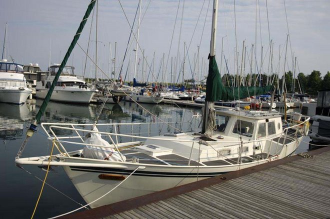
 |
| Very nice, and this was before the paint job. |
Part of the struggle in refitting is getting the order right. This is why Matt's help was invaluable. In order to make the template for the thrust bearing that will carry the AquaDrive that will mate with the coupler that will spin off the engine...you have to pull the shaft.
So you have to remove the coupler:
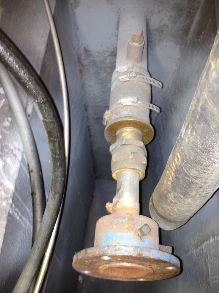 |
| Coupler jobs down here. |
Not shown: the removed coupler and stuffing box. According to Matt, who actually folded himself in place to do this bit while I attacked the hydraulic end, everything came off pretty easily. I actually had a crack at this part previously, which may have helped. The "bilge pit" paintjob is holding up, I see.
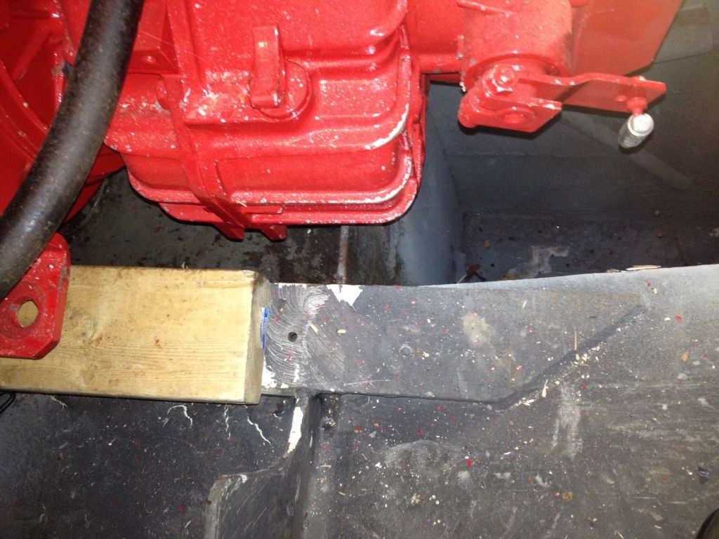
A fresh eye on the engine stringers, currently topped by lumber as standoffs representative of the height of the "soft" engine mounts that will support the engine, confirmed that the engine is more or less "in the zone". A future post will document the process of measurement, thrust bearing template making, and subsequent welding/fabrication.
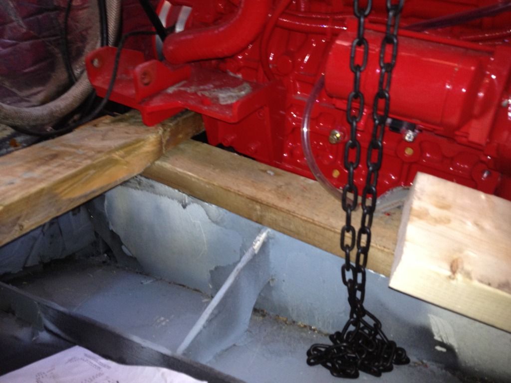 |
| I think I should have another crack at painting this area as it is a little thin. |
Still shiny, but could use a dusting.
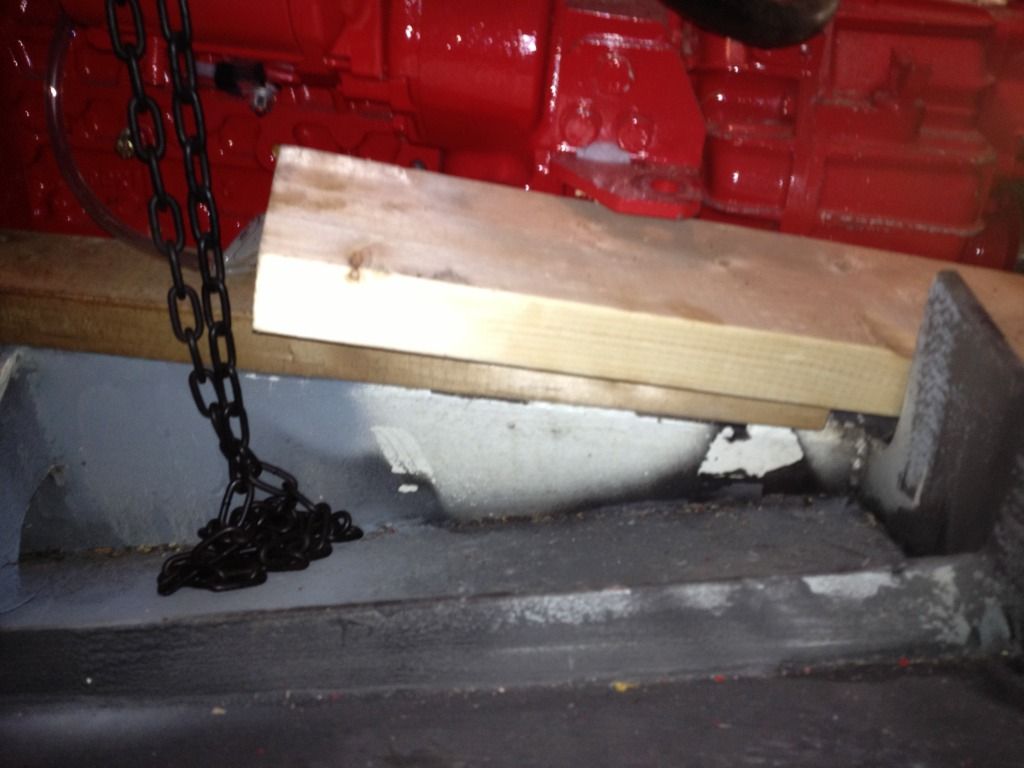 |
| Discussion has centered on making an oak riser topped with sheet metal, or simple HDPE blocks to get the necessary height for the motor mounts. These will be through-bolted to the steel plate stringers. |
 |
| Some grinding remediation might be necessary here, but we won't know until templates are made | | |
When the engine's in place, I need to order a water lift muffler, which I would prefer, if possible, to keep outside of that deep bilge. It's been suggested I could fill that with lead, but I'm thinking "wine cellar". We'll see. Under the engine is another tank I wish to make my 40 gallon third fuel tank.
Next came the hydraulic steering arm or ram, which is more than just a anagram of "arm". As this device is fairly carefully positioned in order to work at the correct angles without rubbing a bigger hole in the stern than is necessary, it became clear that the best method was to unbolt the entire plate. Thirty 4 mm Allen key operations later, some grunting and a frank admiration that the job was done with dressed threads and mere gasketing and NOT the 5200 that glued the roof down and gave me so much grief in the past, the plate was off.
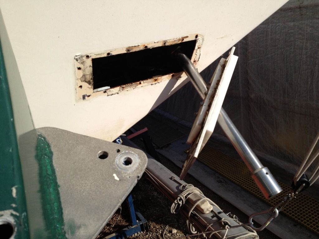 |
| There are robust pins and "cuffs" already stashed away here, but it's a pretty strong method of steering. |
This area will be cleaned up, as will the slightly corroded threads, and the HDPE plastic "sandwich" will be replaced with Starboard, which is more UV-resistant. Care will be taken to replicate the snug, angled passage through which the ram (or arm) passes. I will also use 4200 and butyl tape or some similar combination of sealants/gasketing to keep as much sea water as I can.
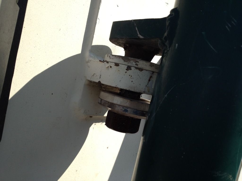 |
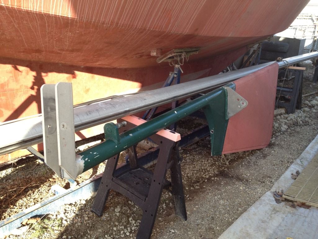
| It turned out to be a two-person job using a two-foot breaker bar and a 1.5 inch deep socket and using the entire rudder as a lever. The upside was that the rudder is lighter than it looks and we lifted it pretty easily off its mounts. |
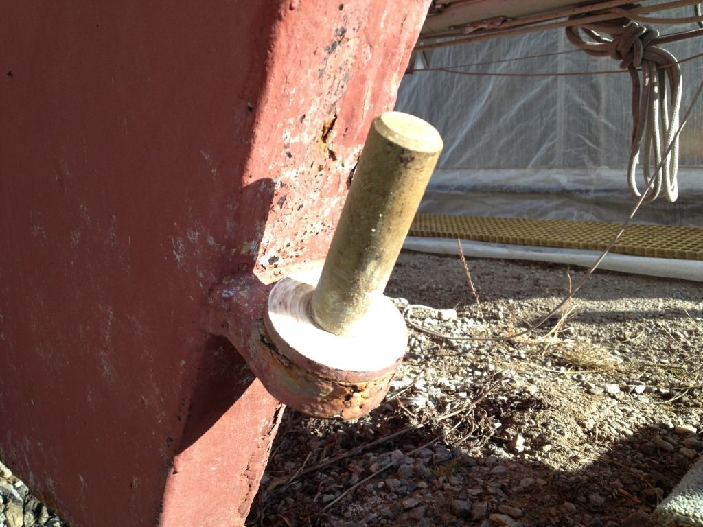
The rudder was next. Freed from the ram, it made a handy lever: the breaker bar and socket were held against the stern, and the stubborn, fairly corroded nut was turned by clocking the rudder itself. That threaded pin will be cleaned up, and a new nut will be through-drilled (as will the pin) to take some sort of cotter pin to keep the nut in place. It's a notable miss on a generally well-built boat that this simple sort of "keeper" was not present in the first place.
 |
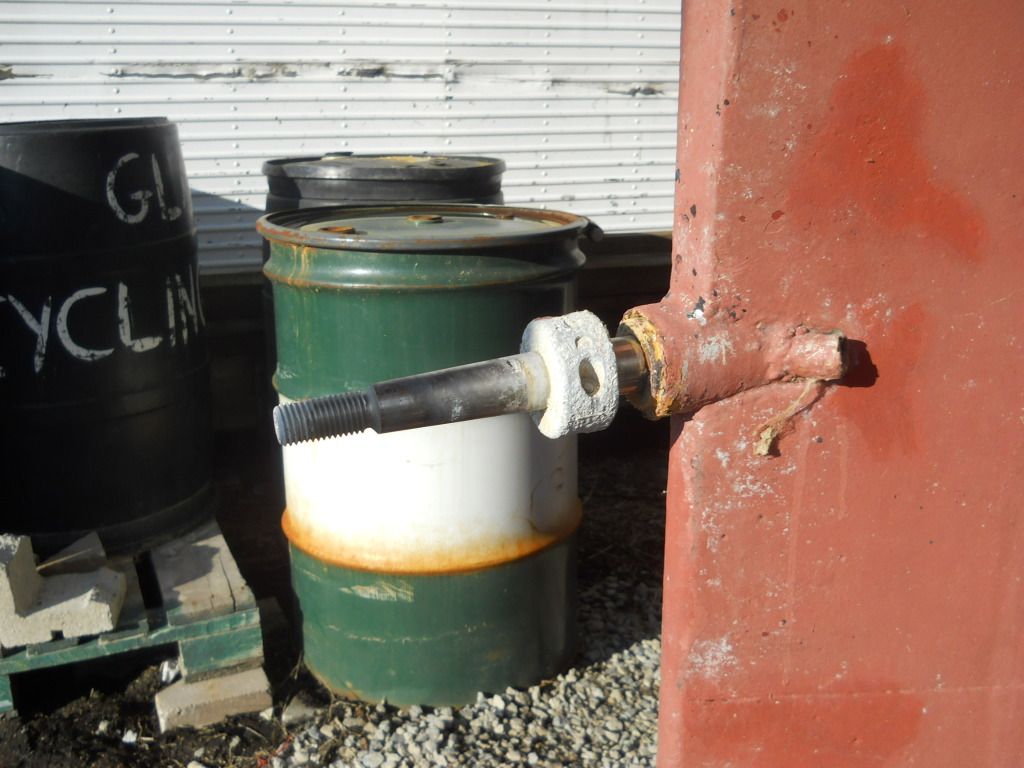
| Will be cleaned up, clearly. I'm going to do the entire hull before launch. |
 |
| Think it's robust enough? I do. |
The bottom
pintle features more Delrin washers that act as bearings. The top pintle/
gudgeon seems to be short a 1-inch spacer, so these will be made.
 |
| Also an opportunity to paint otherwise inaccesible areas |
I like this bit: a massive Delrin insert in the bottom of the rudder. As it sits on another Delrin ring, everything goes smoothly, something I noticed hand-steering via tiller with the hydraulics bypassed.
 |
| Together for the first time: important parts of Valiente (mast) and Alchemy (rudder). |
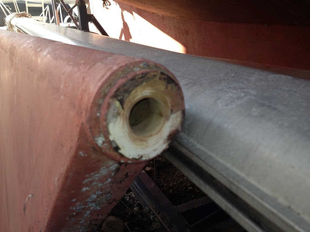
The small hole in the top of the rudder blade is to let in water; there is a similar threaded hole in the bottom. This is in part for draining water that would enter through just being in the water most of the time, but also can be used to deliberately flood the rudder. I'm going to make plugs in order to see how a nominally "empty" rudder steers. I also may have to enlarge the aperature for the new prop, which would involve aluminum welding and yet more measurement.
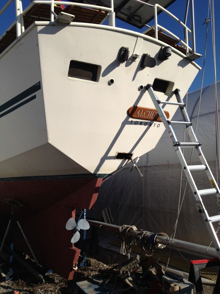 |
| Behold the naked stern! |
Lastly, the original fixed, three-bladed 18 x 13 prop came off, thanks to a bit of fiddling with a prop puller I acquired at some hazard to life and limb by cycling out to North Etobicoke by bicycle last year. Like the great big socket used to remove the pintle nut, it's a single-use tool that is worth the price for that single use. Took about a minute and two swings of my biggest crescent wrench, another rarely used...but absolutely needed...hand tools. I'll keep the old prop as a, God forbid, spare.
 |
| After the bris, the lox! |
Fitting the new prop will happen in the next few days, along with confirmation that it fits when full feathered (I already know that zinc has to go!), after which I'll pull the shaft to check for length and trueness, which I believe means finding a perfectly flat really big tabletop and rolling the shaft to see if there's any sort of wobble. Finally, however, a properly productive day. Sailing is peanuts next to time management.


2 comments:
Good progress Marc. Isn't it amazing how some folks use 42/5200 as an adhesive rather than calk? Will you be able to install cleanout ports on all three diesel tanks including the one under the engine? Where will you mount the shaft zinc if your feathering prop interferes with the one in your picture?
Will the rudder have it's own zincs?
Thanks, Ken. Yes, as I found after unbolting 40-odd bolts on the pilothouse roof that the P.O. had laid down a bead of 5200 where a nice 1/8th inch strip of butyl would've worked just as well...it's tenacious bloody stuff that ate about six titanium sabre-saw blades and about a week of labour.
The tanks already have cleanout ports, about nine inches across. So does the tank under the engine. The reality is that I will have batteries over two tanks and the engine over the day tank, but I will clean them to sparkly goodness BEFORE I bolt all that down, and then will use my FilterBoss fuel polishing system, along with a Baja-style deck filter, to keep everything clean.
The shaft zinc solution will reveal itself when I mount the prop shortly. I will either shave down a new 1.25 inch zinc, or give it up and rely on the zinc supplied with the Variprop, which secures to the cap nut.
Until I drop a length of tight kite string from the inner side of the pintles, I won't know if I need to alter the rudder post. I have a plan to cut out a section and essentially "box" it with shaped aluminum plate, but that's only if necessary and only if I need to. If I have one inch of clearance with the prop blades feathered, I'm good to go, as the shaft and AquaDrive UJ coupler will be isolated to the thrust bearing; they will not be moving.
The rudder will have its own teardrop zincs, as it is made of aluminum, although the Delrin goes some way towards isolating it.
The hull itself will have the usual plate zincs, mostly aft.
Post a Comment